Shims, shims they’re good for your bike, the more you change them, the more the handling goes to…..
Introducing shims to dampen oil flow was an absolute triumph in suspension technology. There’s no doubt that the switch from squishy and harsh orifice damping to using these round little slices of glory improved performance massively, and brought in a whole new world of tuning options. Sounds like great news right?
Of course it is, but the new challenge of figuring out how to adjust the shim diameters, thickness’s and arrangements created the dark art of suspension tuning that we know of today.
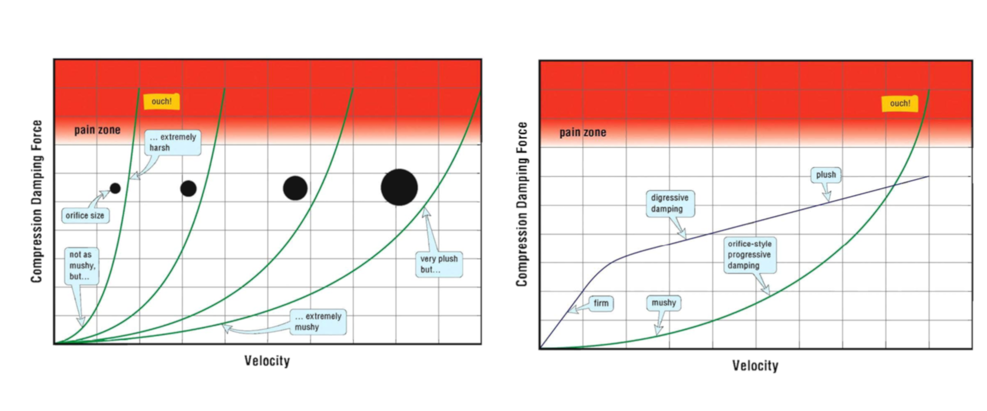
As a quick recap, shims will bend out of the way of the oil flow, making a more linear or digressive damping curve. This gives the suspension good hold up over low speed impacts, but allows the suspension to move on high speed impacts. Compared with orifice damping which was just a hole drilled in a tube, so it offered little to no resistance under low speed, and increased damping exponentially at high speed, causing it to feel harsh.
The graph below is from the Racetech Suspension Bible and shows how increasing the orifice diameter affects the damping curve on the left, and how using a shimstack compares with an orifice on the right.

I have to preface this article with the fact that I have never worked as a suspension technician. However, I do have a masters in engineering, but my time working as a car mechanic with my older brother taught me that the piece of paper they give you at the end of college isn’t much use when you’re wrestling a diesel four wheel drive gearbox onto a spigot shaft.
What I will try to do here then is marry together the literary research I have carried out over the years, with the practical knowledge I have garnered from hanging around suspension technicians.
The question we will try to answer today is, which part of the shim stack should I target to make a rider feel more comfortable?
There are probably technicians who could answer this question just from raw experience, and trial and error. By using an analytical approach though, we can reduce testing time, and document a lot of that information gathered through experience. Every technician has to retire some time, and it’s an awful pity to lose all that knowledge.
Let’s start with what we know already.
From our previous articles, we know the average speed of the suspension movement on different sections of the track, and that we can use dyno’s to measure the suspension damping force effectively for the speed’s we see on the circuit.
What we don’t know, is which part of the shim stack is affected by how much force. If we know the answer here, it becomes straightforward to know which part of the stack to adjust. So how can we calculate the stiffness of each part of a shim stack?
Fortunately, there are lots of very clever people in the world, and one website I came across www.shimrestackor.com, has developed a piece of software that you can input all the shim dimensions from your stack, and it will print out a stiffness graph. You do have to pay a license fee for the software, and for the purpose of this article, I cam across a formula on the site that I could use as a rough substitute to demonstrate my point. The following formula basically calculates the stiffness of each shim, and by adding all the stiffnesses together, you can see how stiff the stack is at each point.

Woah!! What the heck is that?
Don’t get too put off now, let’s just look at this in plain English.
There are a few different symbols in there that mean the following:
K Stack: How stiff the whole shim stack is.
n: The number of shims in the shim stack.
Ki: The stiffness of the i-th shim.
Ei: How stiff a material is.
ti: The thickness of the i-th shim.
vi: How much the shim will squish out when it’s squeezed together.
Ri: What the radius is for the curve of the shim when it’s being pushed out of the way by the oil.
So what we do is calculate out K for each shim, and then add each K value together.
There are many assumptions built in here, and this equation also doesn’t account for crossover shims, or other variations, but as I said, this is a rough estimate.
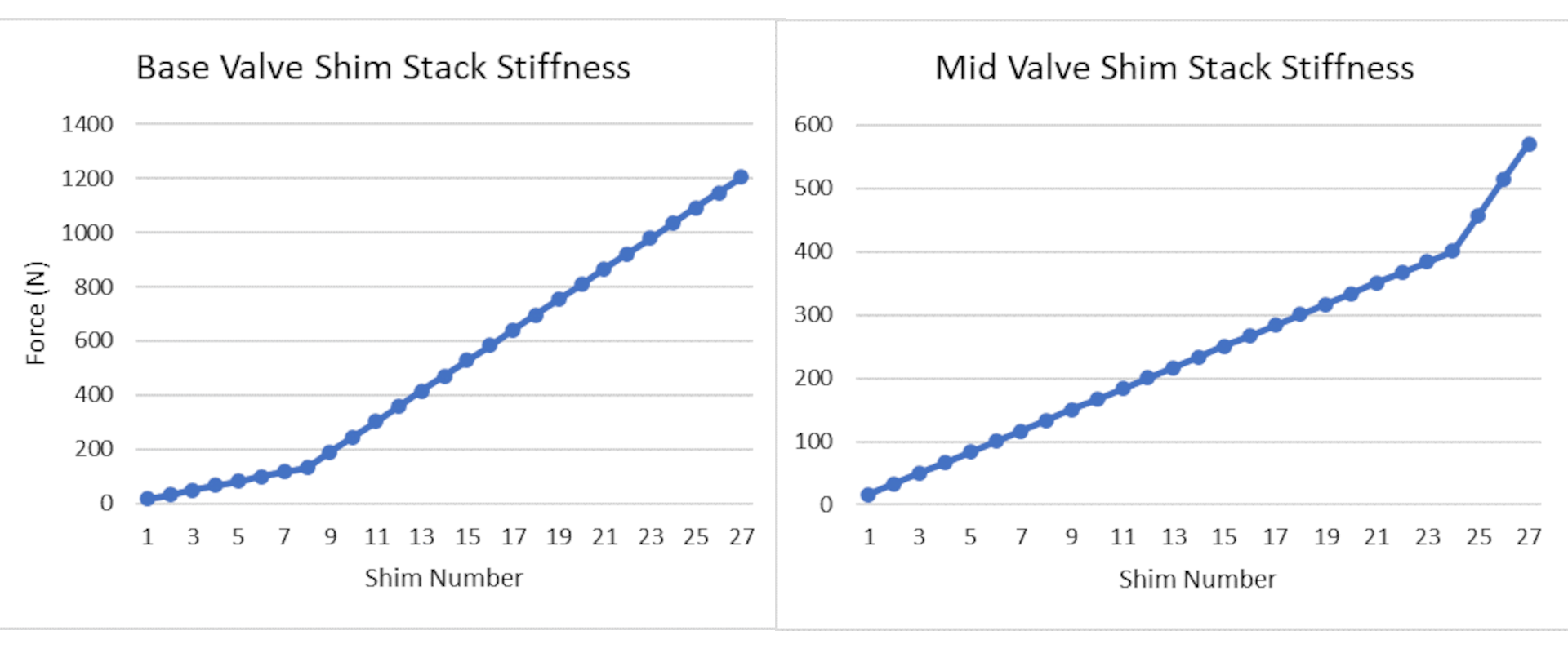
The shim values I am using are the standard settings from a WP XACT fork for the base valve and the mid valve. I just plug in the values from this sheet into the formula above, and it results in the following two graphs:

These graphs show the force created by each shim in the base valve and the mid valve using the formula. There were 27 compression shims in each stack, excluding the clamp shim. What’s strange to me is how the mid-valve maxes out at 600N, while the base valve goes up to 1200N.

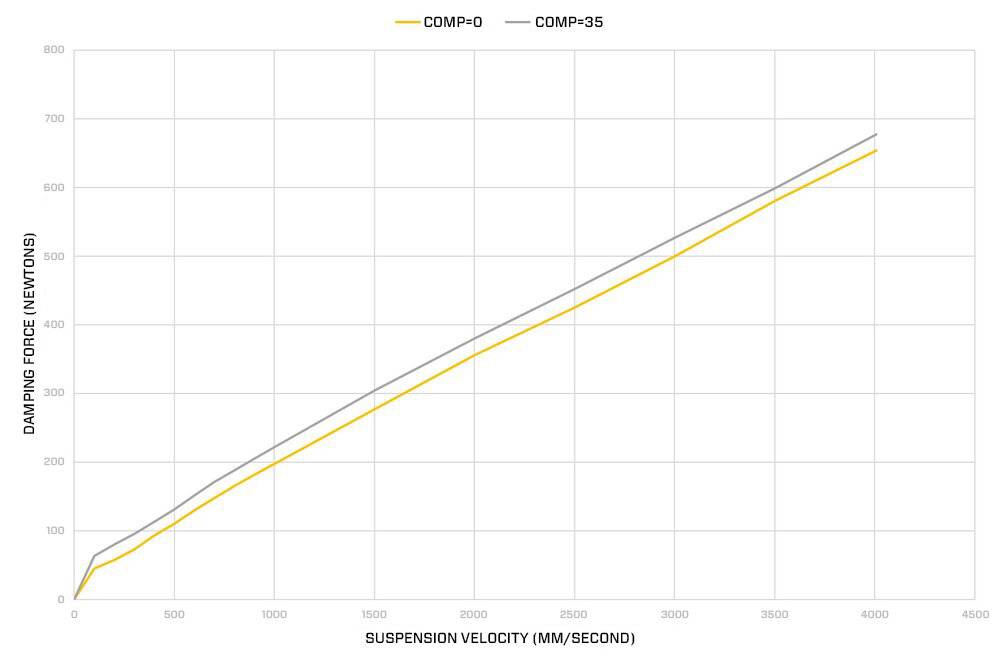
And if you remember from our last article on dyno’s the above graph is from Kreft suspension, and shows the damping force in Newton’s created at speeds from 0m/s up to 4m/s. Our last piece of the puzzle is to know how fast the suspension is moving on the part of the track the rider doesn’t feel comfortable on. There are two ways we can do this, one is to take the average speed of the suspension in compression on that part of the track, or two is to view the actual speed in the Motoklik app.
As an example, if the rider is having an issue on corner entry, the data from the speed of motocross suspension article showed that the average speed on corner entry was 0.506m/s. Working this back through the Kreft graph shows that the average force is around 120N, and working this back again into the shim stack graphs shows that this is around shim 6 on the base valve, and shim 8 on the mid valve.

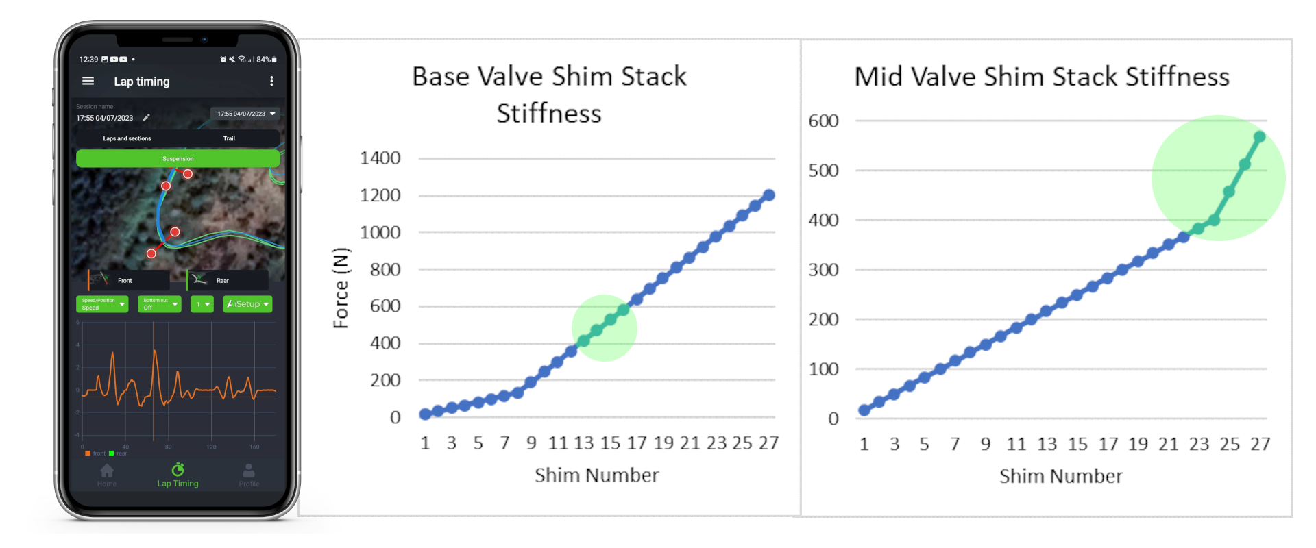
Looking at example two, using the Motoklik app, I have picked a corner entry on the track. If the rider was complaining saying that they feel a harsh hit, we can easily see this in the speed the suspension moves on the graph. Taking this a step further, and assume we don’t want to affect the other parts of the turn, we can isolate the hard hits to between 2m/s and 3.6m/s. Converting this into a force shows that we are between shims 13 and 17 on the base valve, and 22 to 27 on the mid valve.
This whole article is just looking at one particular circumstance, and all of the values and forces can change depending on the type of rider, type of track, and configuration of the shim stack.
I do think it’s clear to see that by taking an analytical approach, we can be much more targeted in the changes we make to shims, and by gathering data continuously, we can build a detailed picture of suspension performance.
If you want to work with the Motoklik system, you can email [email protected] with any questions you have.
Kind Regards,
Jens
P.S.
Thankfully Craig Dixon was on hand to point something out which I missed in the article, please read below to see what else to be aware of:
“This is both correct and incorrect, identifying the shim area is fine but shims do not act as individuals, nor is there an identifiable high speed or low speed area of a shim stack. changing any shim changes the forces across the entire velocity / damping range. For example if we are to make a change to a high velocity shim (#13 to pick a number) and make this part of the damping stiffer, the low speed area will also increase in damping in proportion to the change made, if only a high speed adjustment is needed then we must also change the low speed shim stack (softer) to keep this section at the original damping force.”
